In 2026, PDC cutter placement is becoming a central factor in drilling efficiency, durability, and wellbore quality. A cutter’s position affects load distribution, rock engagement, heat generation, and wear progression across the bit face. Placement decisions should match formation strength, abrasiveness, interbedded layers, and expected drilling parameters. A design that performs well in soft shale may struggle in hard limestone or abrasive sandstone.
How to optimize PDC cutter placement on a bit? Begin with the cutting profile and the expected rock response. Larger cutters can improve stability in selected areas, while smaller cutters may reduce impact damage near aggressive transitions. Blade position also matters. Nose and shoulder cutters often experience higher sliding distance and thermal exposure. Gauge cutters require careful backup support because excessive wear can enlarge the hole or reduce directional control. Back rake, side rake, cutter exposure, blade spacing, and hydraulic coverage should be evaluated together, not separately.
Practical optimization depends on evidence. Bit records, dull grading, torque trends, vibration measurements, and offset-well data can reveal whether cutters were overloaded or poorly supported. Laboratory testing helps, but field conditions remain less predictable. That limitation deserves attention. A placement model may look efficient on paper yet fail after a formation change. Engineers should therefore compare predicted wear with actual cutter damage, then refine the layout for the next run. Small adjustments can matter. A few millimeters of spacing, a different cutter orientation, or stronger shoulder protection may improve drilling response without making the design unnecessarily complex.
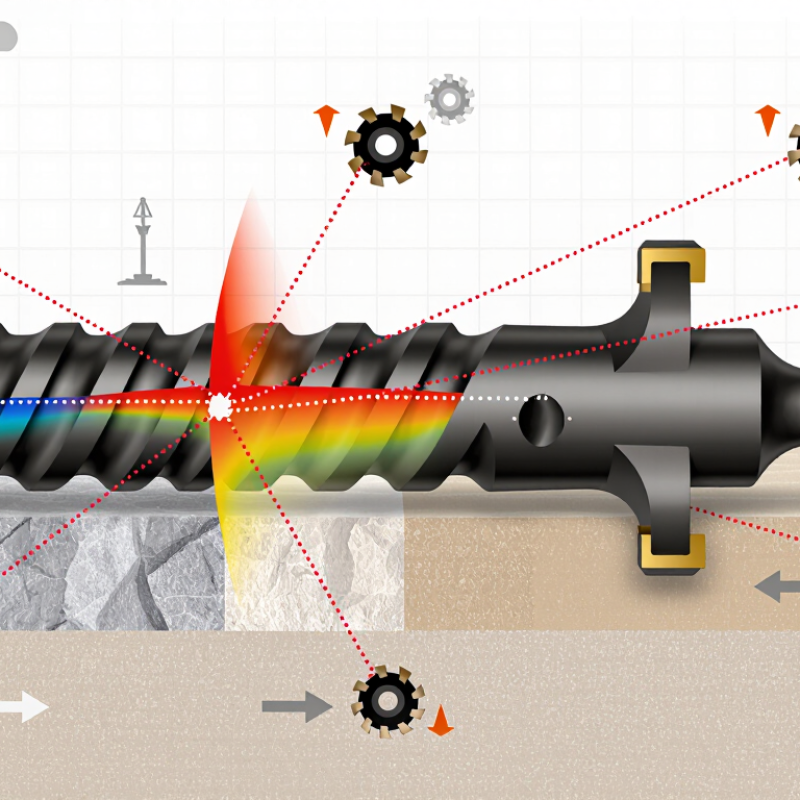
PDC Cutter Placement: Definition, Purpose, and Key Drilling Principles
PDC cutter placement is the planned arrangement of diamond cutters across a drill bit face. It controls how the bit contacts rock, removes formation, and carries drilling loads. A well-designed layout places cutters from the center cone to the shoulder and gauge, creating balanced cutting coverage. Each position matters. Nose cutters often manage high impact loads, while shoulder cutters handle stronger scraping forces and help maintain hole diameter.
The purpose is not simply to add more cutters. Excessive density can reduce depth of cut and increase friction. Wider spacing may improve cleaning, but it can overload individual cutters in hard or fractured rock. Engineers should match cutter size, exposure, back rake, and spacing with rock strength, weight on bit, rotary speed, and expected vibration. Hydraulic flow also matters. Cuttings must leave the cutters before they recut the bottom.
In practice, placement should be checked against torque, temperature, and vibration data from nearby wells. A cutter pattern that performs well in shale may struggle in abrasive sandstone. This is where design judgment becomes important. Laboratory testing helps, but it cannot reproduce every downhole change. I would treat any “best” 2026 layout as a starting point, not a universal answer. Small shifts near the shoulder can change wear behavior noticeably. Test results, drilling records, and post-run inspection should guide the next revision.
How Rock Properties Determine Cutter Position and Cutting Depth
2026 Best PDC Cutter Placement for Better Drilling?
How Rock Properties Determine Cutter Position and Cutting Depth
Cutter placement should begin with rock behavior, not a standard bit drawing. The ISRM Suggested Methods classify rock above 100 MPa UCS as very strong. Such formations usually require smaller cutting depths and stronger cutter support. In softer shale, deeper engagement can improve footage, but excessive depth may create torque spikes and unstable vibration. Small changes matter.
Quartz-rich sandstone adds another problem. Its abrasive grains can round the cutter edge quickly, even when drilling parameters look conservative. SPE drilling studies link higher mechanical specific energy with inefficient rock removal and rising cutter damage. Engineers can respond by reducing cutter exposure, tightening the cutting layout, or increasing back rake. A field test should compare torque, rate of penetration, and MSE over short intervals.
Bedding and natural fractures also change the ideal position. Place more cutters across unstable layers when impact risk is high. Leave enough spacing for cuttings to escape around the cutter face. In anisotropic rock, side rake may need adjustment because the cutter can slide along bedding instead of cutting cleanly. This is where laboratory predictions become imperfect. A caliper log, cuttings inspection, and dull analysis often reveal more than a single strength value. Personally, I would not finalize placement from UCS alone. Confining pressure, moisture, temperature, and bit dynamics can overturn the first design assumption.
Step-by-Step Layout of PDC Cutters on the Drill Bit Face
2026 Best PDC Cutter Placement for Better Drilling?
Step-by-Step Layout of PDC Cutters on the Drill Bit Face
Begin with the bit center, not the gauge. Place smaller cutters near the nose to control torque and reduce tracking. Move outward with slightly larger cutters across the shoulder. Keep radial spacing consistent, but avoid a perfectly uniform pattern. Formation hardness changes across the face. A practical layout uses denser cutter coverage where impact and wear are highest. The IADC Drilling Manual links cutter placement with depth of cut, stability, and hydraulic cleaning.
Set the back rake before final spacing. More negative back rake improves cutter protection but can reduce drilling speed. In soft formations, engineers often reduce back rake and increase exposure. In hard, abrasive rock, stronger support matters more. SPE/IADC case studies commonly report 15% to 30% ROP improvement after optimizing cutter density and depth of cut. These gains vary widely. They depend on weight on bit, rotary speed, hydraulics, and formation changes. One mistake remains common: treating laboratory results as field certainty.
Tips: Mark the face in radial zones. Check nose, shoulder, and gauge exposure separately. Keep cutters clear of nozzle flow paths. Review dull-grade photos after every run. A worn shoulder may reveal poor load sharing. Use torque and vibration data during the next run. If the pattern looks balanced but vibration rises, rethink the layout. Nakne. Ageing cutters also change the design response.
2026 Best PDC Cutter Placement for Better Drilling?
Step-by-step layout reference for distributing 13.44 mm PDC cutters across an 8.5 in (215.9 mm) drill-bit face. The radial zones below represent a balanced example layout that increases cutter density through the shoulder and gauge transition, where drilling speed and wear control are especially important.
How to read the layout: Start near the bit center, then add cutters progressively toward the shoulder. The outer zones use closely spaced cutters to support gauge protection and reduce localized loading. Actual placement should be validated against formation strength, bit profile, hydraulic design, cutter back rake, and expected wear.
Optimizing Cutter Density, Back Rake, and Side Rake for Performance
2026 Best PDC Cutter Placement for Better Drilling?
Cutter placement starts with the formation, not a standard layout. In softer intervals, higher cutter density can improve cutting efficiency and reduce excessive depth of cut. Hard, abrasive rock may need fewer active cutters with stronger support behind them. This balance affects torque, vibration, and cutter wear. Field data matters more than drawings alone. Track weight on bit, rotary speed, torque, rate of penetration, and dull condition after each run.
Back rake controls aggressiveness. A larger back rake angle usually improves cutter protection, but it can reduce penetration and increase energy consumption. Lower back rake may drill faster in uniform rock, yet it can produce unstable torque in interbedded sections. The correct choice depends on strength, abrasiveness, and operating limits. Small changes can be significant. A two-degree adjustment may alter both drilling response and wear patterns.
Side rake helps manage lateral forces and supports smoother cutter engagement. Balanced side rake can reduce tracking problems near the shoulder and gauge. However, excessive side rake may weaken the cutter’s effective support. I have seen layouts perform well in one interval and disappoint in the next. That result is not always a design failure; formation changes are often underestimated. Review cutter exposure, blade spacing, and damaged areas together. Some optimization decisions remain imperfect until real drilling evidence challenges the original model.
2026 Best PDC Cutter Placement for Better Drilling? – Optimizing Cutter Density, Back Rake, and Side Rake for Performance
| Formation / drilling condition |
Typical cutter size |
Recommended starting cutter density* |
Back rake angle |
Side rake angle |
Placement strategy |
Expected drilling response |
| Soft, low-abrasivity shale and claystone |
16–19 mm (5/8–3/4 in) |
Low: approximately 0.35–0.60 cutters/in² |
8–12° |
0–5° |
Use wider circumferential spacing and fewer backup cutters; keep the nose and shoulder adequately covered. |
Higher potential ROP and lower cutting torque, with increased attention to bit balling and cutter impact loading. |
| Medium-strength, moderately abrasive sandstone |
13–16 mm (1/2–5/8 in) |
Medium: approximately 0.55–0.85 cutters/in² |
12–18° |
3–8° |
Balance cutter spacing across the profile; add moderate shoulder and gauge protection for abrasive intervals. |
Balanced ROP, torque, and cutter wear when hydraulic cleaning is sufficient. |
| Hard, abrasive sandstone |
13 mm (1/2 in) or smaller |
High: approximately 0.80–1.20 cutters/in² |
18–25° |
5–10° |
Reduce individual cutter loading with closer spacing and stronger backup coverage, especially at the shoulder. |
Improved cutter survival and smoother torque response, normally with reduced instantaneous ROP. |
| Interbedded shale, limestone, and sandstone |
13–16 mm (1/2–5/8 in) |
Medium-high: approximately 0.70–1.00 cutters/in² |
16–22° |
5–8° |
Use a graduated density profile: more active cutters at the nose and shoulder, with controlled exposure on the cone. |
Better stability and reduced risk of shock damage during changes in rock strength. |
| Hard limestone and dolomite |
13 mm (1/2 in) |
High: approximately 0.85–1.20 cutters/in² |
20–30° |
5–10° |
Favor robust, closely spaced cutters and conservative exposure; reinforce the nose, shoulder, and gauge regions. |
Lower cutter impact stress and improved durability, but higher WOB may be required to maintain ROP. |
| Highly interbedded or impact-prone formations |
13 mm (1/2 in) or smaller |
High: approximately 0.90–1.30 cutters/in² |
22–30° |
0–5° |
Minimize abrupt changes in cutter exposure and rake; use near-neutral side rake to limit lateral impact loading. |
More predictable torque and improved resistance to chipping, with a likely ROP trade-off. |
| Directional drilling or high-build sections |
13–16 mm (1/2–5/8 in) |
Medium-high: approximately 0.65–1.00 cutters/in² |
16–24° |
3–8° |
Keep cutter loading balanced between blades and maintain consistent shoulder and gauge engagement. |
Improved steering smoothness, reduced torque fluctuation, and more stable directional response. |
|
Design note: The ranges above are representative starting windows for fixed-cutter PDC bit design, not universal specifications. Actual optimum values depend on bit diameter, blade count, cutter grade, cutter exposure, hydraulic design, WOB, RPM, torque, formation strength, abrasivity, and impact tendency. Cutter density is expressed as an approximate number of active cutters per square inch of projected bit area; laboratory testing and offset-well data should be used to finalize placement.
|
Testing and Adjusting Cutter Placement for Safer, Faster Drilling
2026 Best PDC Cutter Placement for Better Drilling?
Testing and Adjusting Cutter Placement for Safer, Faster Drilling
Cutter placement should match the formation, not a fixed drawing. Before running the bit, review offset data, rock strength, vibration history, and expected depth. Experienced drilling teams compare these details with the planned cutter exposure and back rake. Small changes can influence torque, heat, wear, and rate of penetration.
The first layout is rarely perfect. I prefer controlled field testing, with clear limits for weight on bit, rotary speed, and flow rate. Record torque trends, penetration changes, cutter wear, and cuttings appearance after each interval. A stable response often matters more than a sudden speed increase. If vibration rises, reduce exposure or adjust the cutter pattern before damage spreads. Do not trust one measurement. Sensor quality and sampling intervals can mislead the analysis.
Tips: Inspect cutters under strong, even light before and after each run. Mark unusual wear locations. Compare them with the borehole direction and formation changes. Adjust only one design variable when possible, so the result remains useful. Keep a written record. It may reveal that an earlier assumption was wrong. That is valuable. Better placement comes from disciplined testing, honest review, and careful adjustment.
Conclusion
Effective PDC cutter placement is essential for improving drilling efficiency, stability, and bit durability. This article explains the purpose of cutter positioning and how rock strength, abrasiveness, heterogeneity, and compressive behavior influence cutter spacing, exposure, and cutting depth. It also presents a practical step-by-step approach to arranging cutters across the bit face, from the center to the shoulder, while maintaining balanced coverage and controlled load distribution.
The discussion further examines how cutter density, back rake, and side rake affect aggressiveness, torque, vibration, and wear resistance. It answers the key question, “How to optimize PDC cutter placement on a bit?” by emphasizing design calculations, laboratory testing, field data, and gradual adjustments. By monitoring drilling response and refining the layout, engineers can achieve safer, faster, and more predictable performance across changing formation conditions.

 Elliott Cutters